How To Make Convex Hull In Image Processing With C#
Convex hull in image processing is a morphological operation, where we encapsulate a shape or and object in an image into a convex shape.
Filter by Category
Convex hull in image processing is a morphological operation, where we encapsulate a shape or and object in an image into a convex shape.
Hit or miss transform is a morphological process for shape detection. We need to use two different structuring elements to find the shapes.
Extraction of connected components in image processing is a morphological process, where we isolate object to a separate image.
Hole filling in image processing is a morphological operation that fills in shapes of black pixels surrounded by white pixels.
Boundary extraction in image processing is one of the basic morphological algorithms with which we extract only the outline of shown objects.
Opening and closing in image processing are morphological operations which are basically sequences of erosion and dilation operations.
Image dilation is one of the fundamental morphological processes, which we demonstrate it here in C# programming language.
Image erosion is one of the fundamental morphological operations and this tutorial explains how it works and demonstrates it in C#.
This tutorial shows how image watermarking works by implementing it with C# and we describe various purposes that watermarks have as well.
This tutorial shows how to use colors for image segmentation applied in C#. I explain the basics of applying it in different color spaces.
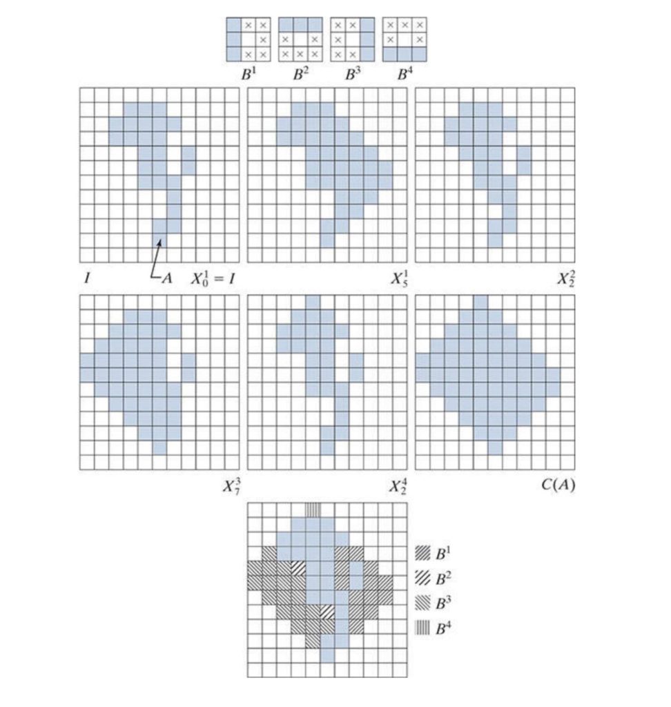
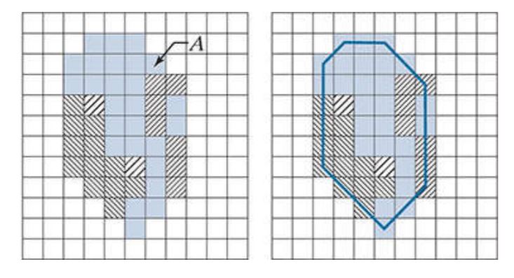
Convex hull in image processing is a morphological process, where we basically envelope an object into a convex shape. In other words, it’s a geometric shape, of which all its inner angles are between 90 and 180 degrees.
For example, let’s say that we have a bunch of points grouped in a certain spot. So if we were to draw a convex hull around them, we need to connect these points. However, we need to connect them in a convex shape.
In other words, if any of the connecting lines completely fit inside the shape, the shape is convex.
If we imagine it in Euclidean plane, where we have continuous lines and shapes, it’s not that hard to understand what it is. But when we’re working with it in image processing, we’re dealing with discrete values – pixels.
Therefore, for simplicity sake, we’re going to work with binary images in this demonstration. Binary images consist only of white and black pixels, or in morphological terms, foreground and background pixels.
We will utilize the hit or miss transform elements using four different structuring elements. In case you’re not familiar, structuring elements are similar to kernels at convolution.
The way it works is that we need to iterate this hit or miss transform to add pixels to our shape in the image. This way, we’ll eventually reach convergence, when no more pixels can be added given the contraits of structuring elements.

If we used only the four structuring elements we mentioned above, we wouldn’t get the most optimal convex shape. Therefore we can use one trick to limit the growth of our shape.
We can use the pixels that lie on the edges of the shape to limit the convergence vertically and horizontally. In other words, we will use them as starting and ending points in the x and y direction.

public static Bitmap ConvexHull(this Bitmap image)
     {
         int w = image.Width;
         int h = image.Height;

         BitmapData image_data = image.LockBits(
             new Rectangle(0, 0, w, h),
             ImageLockMode.ReadOnly,
             PixelFormat.Format8bppIndexed);

         int bytes = image_data.Stride * image_data.Height;
         byte[] buffer = new byte[bytes];
         byte[] result = new byte[bytes];

         Marshal.Copy(image_data.Scan0, buffer, 0, bytes);
         image.UnlockBits(image_data);

         int[][,] se = {
             Structuring_Element.left,
             Structuring_Element.top,
             Structuring_Element.right,
             Structuring_Element.bottom
         };

         int start_x = w;
         int end_x = 0;
         int start_y = h;
         int end_y = 0;

         for (int i = 0; i < w; i++)
         {
             for (int j = 0; j < h; j++)
             {
                 int position = i + j * image_data.Stride;
                 if (buffer[position] > 0)
                 {
                     start_x = Math.Min(start_x, i);
                     end_x = Math.Max(end_x, i);
                     start_y = Math.Min(start_y, j);
                     end_y = Math.Max(end_y, j);
                 }
             }
         }

         result = buffer;
         for (int i = 0; i < se.Length; i++)
         {
             int diff = 1;
             while(diff != 0)
             {
                 diff = 0;
                 for (int x = start_x + 1; x < end_x - 1; x++)
                 {
                     for (int y = start_y + 1; y < end_y - 1; y++)
                     {
                         int position = x + y * image_data.Stride;
                         byte val = 15;
                         for (int kx = -1; kx < 2; kx++)
                         {
                             for (int ky = -1; ky < 2; ky++)
                             {
                                 int se_pos = position + kx + ky * image_data.Stride;
                                 if (se[i][kx + 1, ky + 1] == 1)
                                 {
                                     val = Math.Min(val, result[se_pos]);
                                 }
                             }
                         }

                         if (result[position] == 0 && val > 0)
                         {
                             result[position] = val;
                             diff++;
                         }
                     }
                 }
             }
         }

         Bitmap res_img = new Bitmap(w, h);
         BitmapData res_data = res_img.LockBits(
             new Rectangle(0, 0, w, h),
             ImageLockMode.WriteOnly,
             PixelFormat.Format8bppIndexed);
         Marshal.Copy(result, 0, res_data.Scan0, bytes);
         res_img.UnlockBits(res_data);

         return res_img;
}The binary image, that I used to demonstrate this process on, was the result of segmentation operation. Feel free to check out other posts on image processing and I hope this one was helpful.
You can also download the demo project and try it out yourself.