How To Use Butterworth Lowpass Filter – C# Guide
Butterworth lowpass filter is used to modify images in the frequency domain.
Filter by Category
Butterworth lowpass filter is used to modify images in the frequency domain.
C# tutorial on how to achieve histogram equalization on an image.
In this tutorial we will be talking about intensity level slicing in image processing. What is Intensity Level Slicing It’s a process that highlights pixels in an arbitrary...
This post is a short revision of Contrast Stretch post we already worked on in the past. Where we talked about histogram equalization, which is a little more complex method than...
What is Log Transformation Anyway? Log transformation in image processing is a part of gray level transformations. It works by transforming each pixel individually. It is usually...
Where Do We Start? There are numerous ways you can flip an image horizontally. It’s pretty basic functionality in image processing. I wanted to challenge myself and not just...
Let’s Get Started A very basic problem that we face in image processing is how to scale images without making them look deformed when we want to make it of an arbitrary...
Zero padding an image is useful when we’re convolving it with a filter of certain size. How much padding should we use depends on how big our filter is. What is the purpose...
Gamma correction is a process, which allows you to set the brightness of screen. You can often run into this setting in video games, where you set the brightness of your screen...
A negative image is a complete inversion of an image, we would say to be normal. In other words, dark areas will appear light, and light areas will become dark. More in detail, a...
We use Butterworth lowpass filter to process images in the frequency domain. And by now, I assume you’re already familiar with Fourier transform and how to use it to transform your images into frequency domain.
I wrote a program that demonstrates how fast Fourier transform works. To process colorized images, we need to pass data from each color channel through the transform separately. And when we have frequency data we can filter it, modify it and after we’re done, transform it back into image.
To turn frequency data back into the image, we need to transform frequencies for each color channel separately as well and put the image together once we have all pixel data.
To learn more about the details, I recommend you to check out my other posts about Fourier transform and how to use Ideal lowpass filter in the frequency domain.
Butterworth lowpass filter processes frequency data similarly as ideal lowpass filter. This might not come as a surprise, since both of them are lowpass filters.
Sharp edges and noise contribute to the high frequency data in the frequency domain. So by using lowpass filters, we will remove high frequency data from the image. Hence the name lowpass – passing through low frequencies.
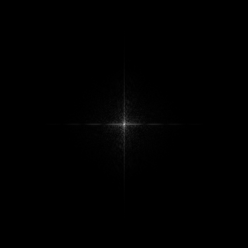
As a result of using such filters, we will blur our image. The smaller the circle in the middle of Fourier transform, the blurier our image will be, once we transform it back to spatial domain. We use the circle in the middle to select which frequencies we want to pass through. Those inside are safe, darkness takes care for those that remain outside.
Now that we described how lowpass filters work in general, let’s take a look what makes Butterworth lowpass filter special.
The main thing about this filter is it’s cut off frequency. With ideal lowpass filter, we cut out frequencies much like cutting shapes out cookie doe.
With butterworth, the transition between the frequencies we want and those we don’t want is much smoother. It fades around the border of the circle. And what makes it special is that we can control the thickness of the fade. If we would have wanted we could have set it so low that it would act just like an ideal lowpass filter.

We can do this with a set of formulas. One formula is going to tell us how far are the frequencies from the center of the image. And another will calculate filter values that will span the whole map of frequencies. So to achieve the result above, we will multiply filter values with frequencies element wise.

M and N are the width and height of the frequency map and u, v variables represent horizontal and vertical position on it.

D0 is the desired max distance from center of the circle, or for technical people also known as its radius. The n variable is called the order of Butterworth filter and this is the variable with which we can control the thickness of the fade around the border of the circle. The higher the order is, the thinner the fade will be.
public static Complex[][][] Butterworth_Lowpass_Filter(Complex[][][] frequencies, double diameter, int order)
         {
             int channels = 3;
             Complex[][][] filtered = frequencies;
             for (int c = 0; c < channels; c++)
             {
                 for (int u = 0; u < Size; u++)
                 {
                     for (int v = 0; v < Size; v++)
                     {
                         //Calculating location from center
                         double d = Math.Sqrt(Math.Pow(u - Size / 2, 2) + Math.Pow(v - Size / 2, 2));
                         filtered[c][u][v] *= (float)(1 / (1 + Math.Pow(d / diameter, 2 * order)));
                     }
                 }
             }
         return filtered;
}There’s an effect that appears on processed images if we use the order of 3 or higher. We call it ringing and it looks like blobs of color on the image.

To avoid this, we can just use orders of 1 or 2 and it works fine. Or in case you’re looking for this kind of “modification”, just turn it all the way up and get a bloby image.
Hope this tutorial was helpful. And you can download the entire project and try it out and play with the values yourselves.